Hux Electronics : Technical Reference Material : IDC Connectors
The Modern Sleeping Dragon, The IDC "Transition" Connector
Most currently manufactured audio equipment use at least some solderless insulation displacement connectors, commonly abbreviated to "IDC", as a way to terminate internal wire links. In general these connectors are reliable and save an enormous amount of time and expense during manufacture. IDC connectors are used in just about anything and at every price point. The use of IDC is generally a good thing but like junk food, too many of them and inappropriate use are bad for the long term reliability of audio equipment.
IDC connections work by the wire being forced into a V shaped receptacle by the pressure exerted by a special IDC squashing tool. The insulation is automatically stripped by the connector at the point where the wire is forced into the V section, hence the name "insulation displacement". The forces inside the IDC are great enough to seal the metal of the wire into the V receptacle and prevent it from oxidizing or coming loose in the future, it is a bit like cold welding the wire into the connector. Providing the connector was put on correctly IDC is a very reliable system. The world as we currently know it is almost entirely dependent on IDC termination of cables in electronic devises.
The most commonly used IDC connectors are standard pitch 0.05 inch "bump" connectors. These use the standard flat ribbon cable that can be bought at most electronic parts supply shops. A standard "bump" connector is nearly always a female, it is called a "bump" connector due to a polarizing bump on one side that stops it being plugged in backwards. A "bump" connector normally plugs into a male "box header" which is usually mounted on the PCB (printed circuit board) where you want the cable to go to. Box headers are sometimes plain and sometimes they have little latches (arms) which are designed to hold the "bump" connector in place. The headers are a firm fit and the "bump" connector can not fall out of a plain "box header" by itself.
It is fairly common for a flat ribbon cable to have a "bump" connector fitted at one end and a "transition" connector fitted at the other end. A "transition" connector crimps onto the cable in the same way that a "bump" connector but then it is soldered directly onto the PCB. In theory a "transition" connector provides a more direct connection at one end of the cable as there are only two points of contact (the wire and the V contact). A "transition" connector can not be unplugged as it is soldered directly to the circuit board.
Failures in "transition" connectors are unfortunately common and are sometimes hard to diagnose. As mentioned a "transition" connector is squashed onto the ribbon cable in the same way that a "bump" connector is but then it is soldered directly onto the circuit board (PCB). The heat during soldering can travel up the pins to the V section and cause it to distort slightly, this results in a compromise in the connection between the wire and the V section. Problems may not show up for years but suddenly a section of the circuit will misbehave. In an audio device this may shown up as failure of part of the circuit or noise or crackling etc. In general the give away is that if you move the ribbon cable the fault will clear, you normally only get one shot at this type of fault finding and so you need to take note of which cable you are moving and which end.
If you move a cable fitted with IDC connectors and the fault clears it will almost always be because of a defective IDC crimp and it will nearly always be in the "transition" connector end if one is fitted. Often the fault will not return in the short term and you will not be able to provoke it again, the mistake that many people make at this point is that they think that they have cured the fault. Re-crimping the connector will not help as the connection between the V section and the wire has been compromised and is probably oxidized. The fault will always return at a later date and so must be dealt with.Following is my approach to standard pitch IDC connector faults : If the fault is in a "bump" connector end you must fit a new connector, re-squashing the old connector onto the cable is not a fix. Depending on the individual case I would normally make a new "bump" connector loom. Sometimes it is better to chop off the old connector, shorten the loom and fit a new connector. Sometimes it is better to simply add a new connector next to the defective one. In all cases I use a set-square and mark the cable with a pen so that I can put the new connector on as squarely as possible. It is best to use a proper IDC fitting tool but I have used a vice and other means to fit new connectors. The main thing is to apply even pressure across the entire width of the connector while squashing it onto the cable.
If the fault is proven to be in a "transition" connector then the fix is more difficult. I mark everything so that I wont forget how it went together. I then break the back off the "transition" header (snip off the little sections on each side and the back will come off), then I pull out the cable. Now the pins must be heated with a soldering iron one at a time (solder side) to be pulled out one at a time (component side). I do not recommend trying to de-solder an intact "transition" header as this will usually cause more damage to the PCB than simply destroying the header and extracting each pin one at a time (been there, done that). Once the pins have been removed use a de-soldering iron or solder-wick to clean the PCB holes. You now have two choices (1) fit a standard box header, or (2) solder the wires directly to the PCB. I have never opted to fit a new "transition" connector as I think that they are a waist of space and will simply fail again.
I tend to fit a standard "box header" as per option (1) where ever possible and then fit a "bump" connector to the soggy end of the cable. If a "box header" wont fit due to a lack of space then I tend to opt for soldering the ribbon cable directly to the circuit board as per option (2), this is a slow and tedious process and looks like crap, but is very reliable.
There are many other types of IDC connectors, each with pro's and con's but I wont go into them here. The biggest evil of the modern pro audio world (apart from hype) is the "transition" connector, lets hope your life does not depend on one.
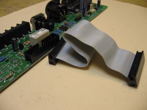
Above shows the all too common flat ribbon cable with a "transition" connector at one end soldered to the circuit board (left hand side of pic) and a "bump" connector at the other end (right side of pic).
Above shows a "box header" fitted after I have ripped out the "transition" connector (gently of course).
Above shows the complete system ready to go, the "box header" is fitted on the PCB and a complete "bump" to "bump" cable is ready to plug in. If for some reason the "bump" connector IDC's fail in the future (fairly rare) then it is a breeze to make up a new cable and just plug it in.
Other Faults
I have seen quite a few faults where the IDC pins in "bump" connector looms have failed, this is usually in cases where the IDC pins are carrying substantial DC current, such as when used as the internal connecting looms in a mixing console, the problem naturally varies with how the connectors are used in the console's design. There are also cases where the factory has simply failed to crimp the "bump" looms properly at the time of manufacture (usually noted because multiple IDC's are found to be defective). On the other hand I have seen many 20+ year old mixing consoles and other bits of tackle where the factory fitted "bump" connector looms are still working properly, again this depends on the electronic design (i.e. how the bits are used and how well they were fitted).
Molex IDC Connectors
The name Molex is a generic term for this type of connector, it does not indicate that the Molex company made them. Molex style connectors with IDC can sometimes be repaired by soldering the wire directly to the V crimp if a fault occurs, sometimes you can re-force the wire back into the IDC section (the cure varies with the problem). More often than not it will be the female contact in the Molex that is at fault and the connector should be chopped off and replaced. In the non-IDC versions of Molex connectors the individual pins can be replaced (if you have the correct brand pins).
Other Types of IDC connectors
There are many other types of IDC connectors used in pro audio electronics including Krone, "D" type with IDC, modular telephone types (inc RJ45 cat-5 connectors) etc. Krone are normally only used externally and are reliable (some folks believe otherwise but this is not true). Faults can usually be cured by re-punching the cable back into the Krone block and a Krone can be punched and re-punched many times as long as a fresh bit of cable is punched into the block. Modular telephone style connectors are not normally used in analogue audio but are common for data and other things, simply chop off and replace these if faulty. The IDC versions of good old "D" connectors seem to be very reliable and I have never had any problems with them.
There is a new terror of the IDC world, these are a 0.05" pitch connector called "Picoflex" and they are turning up in power amplifiers and other places. Picoflex connectors are reliable when left alone but are very easy to break when you unplug them. If you encounter these little beasties, run fast. So far I have not seen these connectors fail by themselves, I have seen many broken ones after repairs by "others" (and by me, when I first met these little terrors).
Regards, Warren Huck, Hux Electronics, 15/05/06